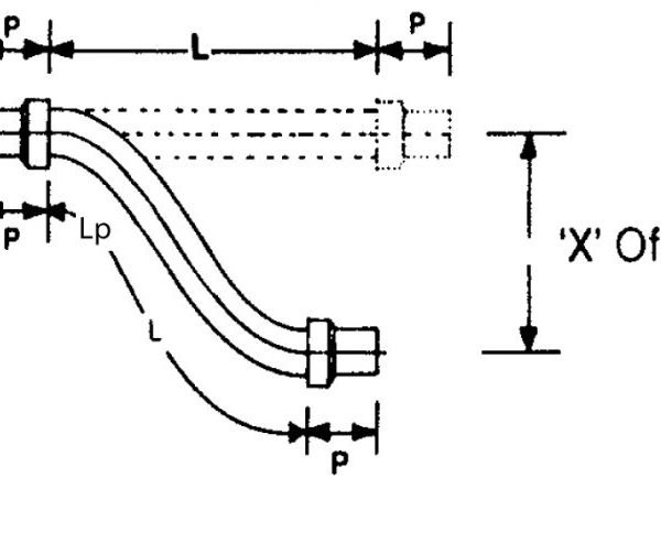
1. Offset Motion
Offset motion occurs when one end of the hose assembly is deflected in a plane perpendicular to the longitudinal axis with the ends remaining parallel.
Formula: L=√6RX+X² Lp=√L²-X²
L = Live hose length (inches).
Lp = Projected Live Hose Length (inches).
R = Minimum Centre Line Bend Radius for constant flexing (inches).
X = Offset Motion to one side of Centre line (inches).
* Formula must only be used in inches
Note 1: when the offset motion occurs to both sides of the hose centre line, use total travel in the formula; i.e. 2 times ‘’X’’
Note 2: The offset distance ‘’X’’ for constant flexing should never exceed 25 percent of the centre line bend radius ‘’X’’
Note 3: If the difference between ‘’L’’ and ‘’Lp” is significant, exercise care at installation to avoid stress on hose and braid at the maximum offset distance.
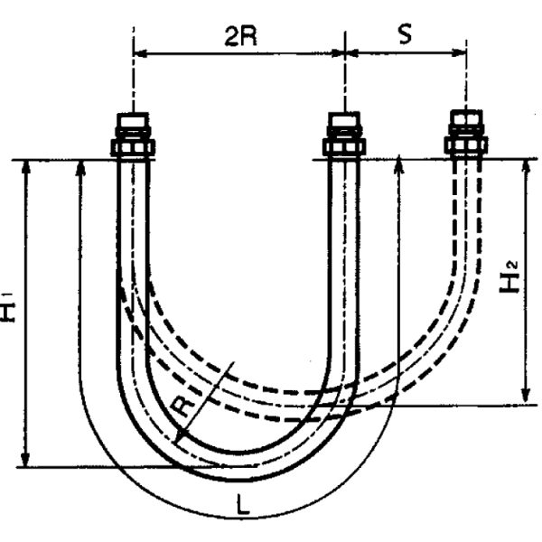
2. Horizontal Movable Pipe System
L= 4R+1.57S.
H1= 1.43R+0.785S.
H2= 1.43R.
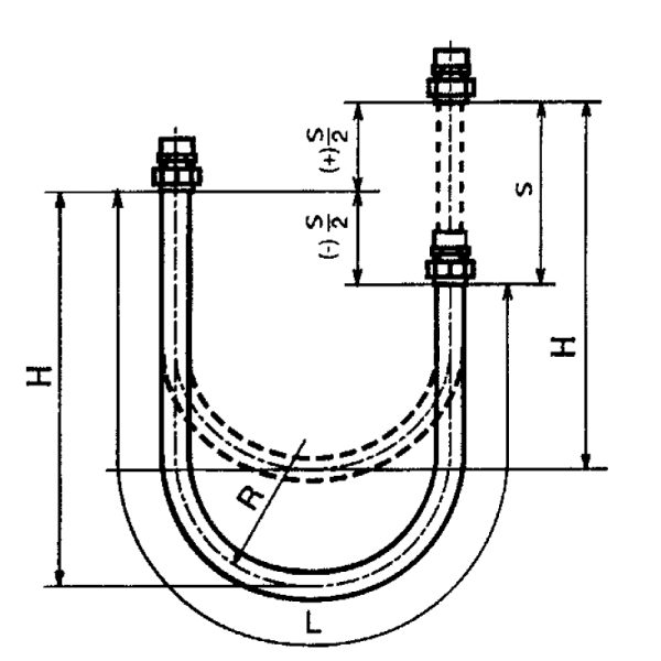
3. Vertical Movable Pipe System
L=4R+.
H=1.43R+.
Illustration of Mark
S: Volume of Variation.
L: Length of Variation.
0: Angle of Variation.
π: Pi 3.142.
R: Min centre line bend radius for constant flex.
Lp: Project live hose length.
Trust us for expert advice and professional service
Contact Us